
A high-performance solar power system relies not just on the quality of panels and inverters, but critically on the correct installation of its lifelines: the photovoltaic (PV) cables. Improper installation can lead to significant power losses, safety hazards like fires or electric shocks, and costly system failures. This comprehensive guide, brought to you by JZD Cable, walks you through the professional best practices for installing PV cables to guarantee a safe, efficient, and long-lasting solar energy system.
Phase 1: Pre-Installation Preparation (Foundation for Compliance)
1. Cable Selection: Never Compromise
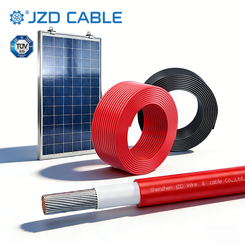
Using standard cables is a critical mistake. Always opt for photovoltaic-specific cables that meet stringent international standards.
- Type & Standards: Use cables certified to EN50618 (or equivalent), such as H1Z2Z2-K. These are engineered for solar applications with superior UV resistance, wide temperature tolerance (-40°C to 120°C), weather resistance, and flame retardancy.
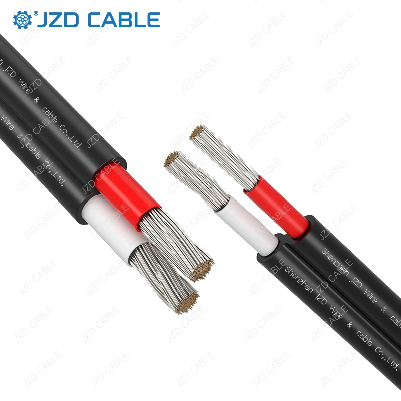
- Conductor: Prefer tinned copper for optimal conductivity and corrosion resistance. Ensure voltage drop is limited to ≤2% on the DC side and ≤3% on the AC side over the run.
- Insulation/Sheath: Cross-linked polyolefin (XLPO) is the material of choice, offering excellent durability and a rated voltage of ≥1500V DC / 1000V AC.
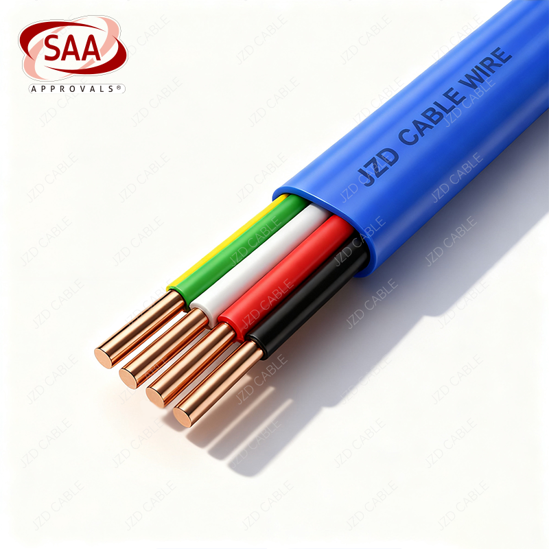
- Color Coding: Adhere to standard color codes for easy identification and maintenance: Red (DC positive), Black (DC negative), and for AC: Brown/Black, Blue, Green/Yellow (earth).
2. Tools and Materials Checklist
Gather the right tools before starting: Cable cutters, wire strippers, crimping tools, multimeter, megohmmeter (insulation tester), heat gun, cable pullers, and fixing clamps.
Essential materials include: IP67 or higher waterproof junction boxes, MC4 connectors, heat-shrink tubing, waterproof sealing tape, cable ties, cable trays/conduits, and grounding strips.
3. Route Planning: Avoid Hazards & Minimize Loss
- Shortest Path: Plan the most direct route from panels to inverter and to the grid connection point to minimize length and resistive losses.
- Hazard Avoidance: Route cables away from heat sources (inverter vents, exhaust pipes), sharp edges, high-vibration areas, vehicle pathways, and potential water accumulation zones.
- Separation: Maintain a minimum distance of 10cm between DC and AC cables when run in parallel. Use insulated barriers at crossing points.
Phase 2: Main Installation Methods & Construction Standards
1. Roof Mounting (Most Common)
- Fixing: Run cables along dedicated channels on mounting structures. Secure with UV-resistant nylon cable ties every 1.5m horizontally. Use anti-drop clamps every 2m for vertical runs.
- Protection: Use flame-retardant PVC/CPVC conduit for protection, especially when passing through walls or roofs. Always use rubber grommets at conduit entries to prevent insulation damage.
- Joints: All splices must be inside IP67-rated junction boxes. Never leave connections exposed. After crimping, seal with 3 layers of waterproof tape and a layer of adhesive-lined heat-shrink tubing.
2. Direct Burial (For Long Outdoor Runs)
- Depth: Bury cables at a minimum depth of 0.7m in non-frost regions and 1.2m (below frost line) in frost regions. Increase to 1.0m in agricultural areas.
- Bedding & Cover: Lay a 100mm bed of fine sand in the trench. Place the cable and cover with 200mm of sand before adding warning tape and concrete protection tiles or bricks on top.
- Conduit for Critical Sections: Use robust MPP or CPVC conduits (inner diameter ≥1.5x cable diameter) when under roads or in risky areas. Use concrete encasement for road crossings.
- Buried Joints: Place inside specially designed, concrete-protected boxes filled with waterproof gel, buried at least 0.5m deep.
3. Cable Tray/Ladder Installation (Indoors/Factory)
- Segregation: Use separate trays or layers for DC, AC, and control cables, maintaining a 50mm gap. Place high-current cables on the bottom.
- Fixing & Grounding: Fix cables horizontally every 1.5m and vertically every 2m. Ensure the cable tray is reliably grounded at both ends and every 30m (ground resistance ≤4Ω).
- Heat Management: Do not fill the tray beyond 40% capacity to allow for proper heat dissipation and future expansion.
4. Conduit Installation (For Confined Spaces)
- Conduit Size: Internal diameter must be ≥1.5 times the cable diameter. For multiple cables, fill ratio should be ≤40%.
- Bending Radius: Maintain a minimum bending radius of 15 times the cable diameter (20D for armored cables). Avoid sharp bends.
- Conduit Ends: Use bell ends or rubber grommets to prevent insulation abrasion.
Phase 3: Critical Construction Details (Safety & Longevity)
1. Bending and Pulling
- Always respect the minimum bending radius (15D-20D). Never make sharp, acute-angle bends.
- Pull cables smoothly at speeds ≤3m/min. Use guide rollers and avoid dragging cables on rough surfaces.
2. Connector & Splice Integrity (High-Failure-Point)
- MC4 Connectors: Keep contacts clean, crimp correctly using the proper tool, and ensure the locking mechanism clicks securely. Always use the provided rubber seal.
- Crimping & Sealing: Strip wire to the exact length required by the terminal. After crimping, use adhesive-lined heat-shrink tubing followed by waterproof (butyl) tape for a hermetic seal.
- Minimize Joints: Aim for ≤1 splice per 500m of cable run. Fewer connections mean higher reliability.
3. Grounding & Lightning Protection
- Ground all metallic parts: cable shields (if present), cable trays, and conduit ends. Achieve a ground resistance of ≤4Ω.
- Integrate the DC negative grounding electrode, AC neutral, and all equipment enclosures into a single, unified grounding system for protection against faults and lightning.
4. Labeling & Documentation
- Install clear, durable tags at both cable ends, junctions, and distribution points (showing specs, route, voltage).
- Maintain as-built documentation: cable route maps, lengths, splice locations, and all test data.
Phase 4: Post-Installation Testing & Commissioning (Mandatory)
Do not energize the system before completing these tests:
- Visual Inspection: Check for physical damage, secure fixing, proper sealing, and clear labeling.
- Insulation Resistance Test: Using a megohmmeter, test insulation between conductors and each conductor to ground. Results should be ≥1000 MΩ-km at room temperature.
- Continuity & Polarity Test: Use a multimeter to verify correct polarity (DC+/DC-) and phase sequence (AC), and check for shorts or open circuits.
- Voltage Drop Test: Under full load, measure the voltage drop on DC and AC lines to confirm they are within the ≤2% and ≤3% limits, respectively.
- Grounding Test: Measure the grounding system resistance to ensure it is ≤4Ω.
Conclusion
Proper PV cable installation is a non-negotiable aspect of a quality solar project. By following this guide—selecting the right PV cable like those from JZD Cable, meticulous planning, adhering to installation standards, and rigorous testing—you ensure the safety, performance, and durability of the entire photovoltaic system. Investing time in correct installation prevents costly future repairs and maximizes your return on investment from solar energy.
For premium, certified photovoltaic cables that form the reliable backbone of your solar installation, explore our products at jzdcable.com.