

Solar DC cables are costly yet frequently overlooked. Many substitute standard wires for dedicated PV Cable. However, PV systems require 25–30 years of durability against UV, heat, moisture, and 1500V DC. The wrong cable fails in 3–5 years, causing insulation breakdown and arc fires. This article covers PV Cable engineering: materials, failure modes, derating, wiring, and sourcing.
What is PV Cable?
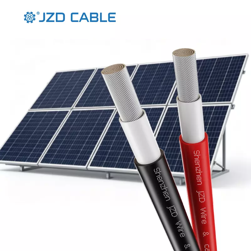
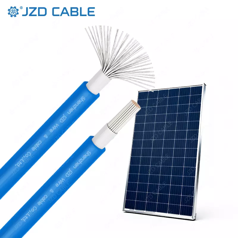
PV Cable is a specialized single-core cable designed specifically for the DC side of solar power systems. It is not merely a “tinned copper wire with black insulation” but an industrial component optimized at the material science level for extreme outdoor conditions. Modern PV cable product lines typically cover mainstream standards ranging from UL 4703 to TUV/IEC 62930.
1. Dual Standards: European/IEC and North American
In the global market, PV Cable primarily follows two standard systems:
- European/IEC System: EN 50618 / IEC 62930 (Type H1Z2Z2-K). This standard typically rates 1500 V DC and 120°C. Conductors use tinned annealed copper (Class 5 flexible stranding), and both insulation and sheath are halogen-free cross-linked polyolefin. Its core requirements are Low Smoke Zero Halogen (LSZH), flame retardancy, and extreme weather resistance.
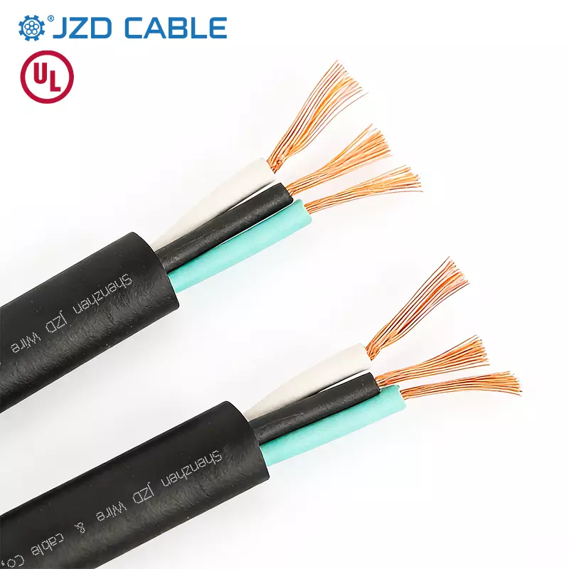
- North American System: UL 4703 (PV Wire). This standard covers 600V, 1000V, and 2000V DC. Conductors can be tinned or bare copper, usually using XLPO insulation with an operating temperature range of -40°C to 120°C. UL 4703 emphasizes cold bend testing and wet-location performance.
2. The Material Barrier: E-Beam Cross-linking and XLPO
Standard XLPE cables generally use chemical cross-linking, while high-performance PV Cables widely adopt electron-beam (E-beam) irradiation cross-linking of XLPO (cross-linked polyolefin) materials. This process breaks and recombines polymer chains, forming an extremely dense three-dimensional network that gives PV Cable two critical properties:
- The insulation layer will not melt or drip at high temperatures of 120°C or even 150°C.
- It effectively blocks the growth of “water trees” under high-voltage DC electric fields, which is the material science foundation for ensuring a 25-year lifespan.
Why Standard Cables Cannot Replace PV Cable
Using standard cables in a PV system is not a matter of “performance degradation” but “fatal failure.”
- The Double Strike of UV and Thermo-oxidative Aging: Standard PVC insulation rapidly loses plasticizers under prolonged UV exposure, causing the insulation to become brittle and crack. Once the sheath cracks, moisture invades, and the DC electric field can instantly trigger tracking. High-quality PV Cables are designed to withstand UV exposure of 2400 kWh/m² and carry a 25-year UV warranty.
- Ampacity Differences at High Temperatures: Rooftop module backsheets and cable trays easily exceed 70°C or even 80°C in summer. Standard cables (rated 70°C) suffer sharply reduced lifespans in this environment. In contrast, PV Cables rated at 120°C have about 2.3% lower line loss than standard PVC cables at 50°C ambient, retaining greater safety margins in tropical projects.
- Short-Circuit Withstand and Conductor Structure: PV Cables have a short-circuit withstand temperature of 200°C (for 5 seconds), while standard PVC cables are usually only 150°C. In a DC arc fault, this 50°C difference determines whether the insulation will carbonize and propagate. Additionally, PV cables generally use tinned copper conductors, significantly extending conductor life in humid, salt-mist, and coastal environments.
Ampacity and Derating of PV Cable: Real Rooftop Calculations
Many design drawings specify PV Cable sizing by directly checking nominal ampacity, which is extremely dangerous. According to NEC 690.31(C), PV source circuits must use 90°C-rated conductors. However, in actual derating calculations (NEC 310.15), multiple factors must be multiplied: ambient temperature correction (approx. 0.82 for 90°C conductors at 50°C rooftop), conduit/tray fill derating (potentially as low as 0.70 for more than 3 current-carrying conductors), and rooftop height adjustment (an additional 33°C ambient temperature for conduits within 7 inches of the roof).
Example: A nominal 40A 10 AWG PV Cable, when installed on a 50°C rooftop, in conduit, and bundled with multiple cables, may have an actual allowable ampacity plummeting to around 23A. PV Cable rated at 120°C retains a larger current margin in derating calculations, reducing unnecessary conductor upsizing and achieving a better balance between copper costs and long-term safety.
PV Cable vs. USE-2: The Trade-off Between Compliance and Cost
In the North American market, USE-2 is sometimes used as a cheap substitute for PV Cable, but engineering procurement must note the following boundaries:
- Voltage Limitation: USE-2 is mostly rated 600V and cannot be used in 1000V/1500V systems. Mainstream UL 4703 PV Wire covers 1000V and 2000V, directly matching modern high-string-voltage DC systems.
- Flame Retardancy Blind Spot: Cables marked only as USE-2 have not passed flame tests like VW-1 and must not enter building interiors or conduits. If array wiring needs to enter an inverter room or indoors, cables marked with PV Wire must be used.
- Physical Structure: PV Cable typically has thicker insulation and a denser sheath to handle pulling friction and mechanical damage in harsh environments.
How to Wire Solar Panels
Having completed the cable specification and derating calculations, the craftsmanship during actual installation and connection is often the “last mile” that determines whether the system survives 25 years. Wiring involves not only physical connections but also electrical topology and protection.
1. String Topology: Series for Voltage, Parallel for Current
- Series: Connect the negative of the first panel to the positive of the second. Series increases system voltage, reduces line loss, but keeps total current constant. This is the primary method for reducing cable costs and voltage drop in commercial projects.
- Parallel: Connect all positives together and all negatives together. Parallel increases system current but keeps voltage constant. Typically used for small off-grid systems or scenarios with partial shading.
- Engineering Tip: Before connecting to a combiner box or inverter, always verify polarity and open-circuit voltage (Voc) with a multimeter to ensure correctness before termination.
2. Connector Termination (MC4 Connectors)
Modern PV wiring almost entirely relies on MC4 connectors. The quality of PV Cable wiring depends heavily on the crimping process:
- Compatibility: Metal pins must match the PV Cable size. For example, 4mm² and 6mm² cables require different sizes of crimp terminals.
- Crimp Force: Professional crimping tools must be used to ensure pull-test compliance. Loose or poorly connected MC4 joints will create contact resistance under high load, causing localized heating or even fire.
- Moisture Sealing: After insertion, you should hear a “click” and tighten the waterproof nut to prevent rainwater from wicking into the conductor core via capillary action.
3. Cable Routing and Physical Protection
- Strain Relief: Leave a slight service loop (typically a “U” shape) between modules to prevent connectors from being pulled directly when modules move due to thermal expansion or wind loads.
- Tying and Securing: Use UV-resistant nylon zip ties or cable clips. Cables must not drag directly over sharp roof edges or metal rails; add protective sleeves or use cable trays.
- Avoid Direct Sunlight and Water Pools: Try to keep cables hidden beneath module backsheets. If elevated, ensure no sagging water accumulation points exist in the middle of the run.
4. Grounding and Lightning Protection Routing
Module metal frames and mounting structures must be solidly grounded. During wiring, a grounding conductor of the same rating as the PV Cable (usually bare copper or green/yellow) must be laid simultaneously. Use dedicated grounding washers or clamps to ensure equipotential bonding of the grounding system.
Supply Chain Verification and Product Options for PV Cable
Whether in early design or on-site crimping, the project ultimately relies on specific product procurement. In commercial and utility-scale projects, product markings alone are insufficient; verification must penetrate compliance certifications and specific product configurations:
Standard Copper Solutions:
- UL 4703 PV Wire: 600V/1000V/2000V DC, tinned or bare copper, XLPO insulation, -40°C to 120°C.
- TUV/IEC 62930 H1Z2Z2-K: 1500V DC, tinned annealed copper Class 5, halogen-free cross-linked polyolefin, rated 120°C.
Lightweight / Cost-Sensitive Solutions:
- Aluminum Conductor PV Cable: 1500V DC/1000V AC, XLPO insulation, -40°C to 90°C.
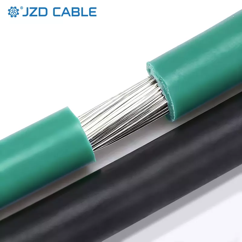
- Tinned Copper-Clad Aluminum (TCCA) PV Cable: 1500V DC, approximately 40% lighter than pure copper, with a tin layer for oxidation protection.
Special Routing Solutions:
- Twin-Core Parallel PV Cable: 2×4mm², 2×6mm², etc., simplifying the routing path from string to inverter.
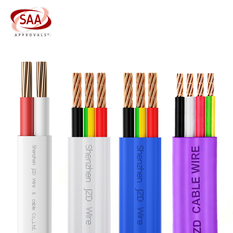
Regarding certification verification, such PV cables typically need to hold UL 4703, TUV 2PfG 2645/08.20, IEC 62930, VDE, SAA, and CB certifications. For projects exporting to Europe, focus on TUV certificates; for North American projects, confirm UL 4703 listing and NRTL evaluation reports.
Conclusion
PV Cable selection isn’t about paying more—it’s about matching materials and certifications to a 25-year outdoor DC environment. From XLPO insulation resisting thermal aging and water trees, to proper crimping and strain relief, every detail matters. Addressing derating, failure modes, and certifications during design is far cheaper than replacing cables during O&M.
For specifications, certification documents, or bulk supply solutions for PV series (PV Wire / H1Z2Z2-K / Aluminum / TCCA / Twin-Core), please contact us.