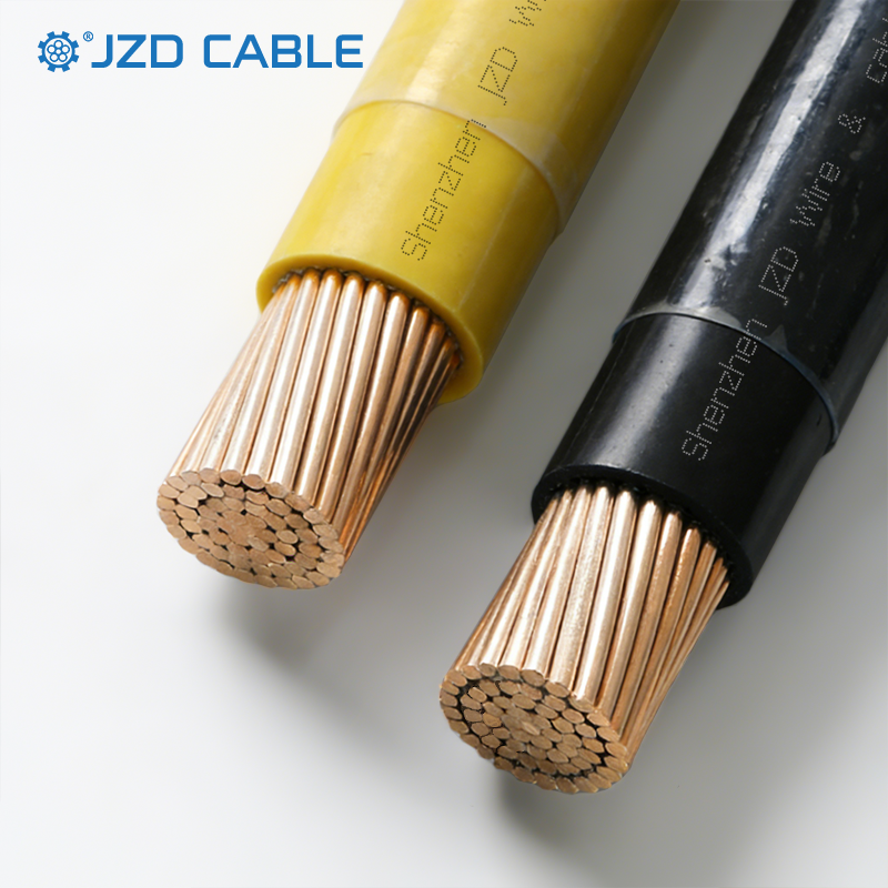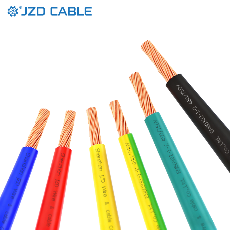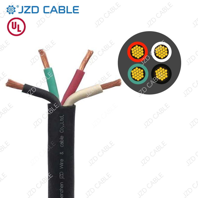


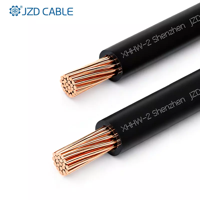
XHHW-2 is the standard building wire for North American commercial and industrial projects. Its XLPE insulation provides a 90°C dry/wet rating, making it suitable for conduits, cable trays, and outdoor exposed runs. But XHHW-2 ships with two conductor options: copper and aluminum. Both share identical insulation and voltage ratings, yet the conductor metal determines ampacity, weight, termination method, and lifecycle cost.
This guide compares copper and aluminum XHHW-2 from an engineering perspective, covering conductor metallurgy, ampacity derating, termination requirements, and application suitability.
Copper vs. Aluminum XHHW-2 at a Glance
| Dimension | Copper XHHW-2 | Aluminum XHHW-2 |
| Conductor material | Bare copper per ASTM B3/B8 | AA8000/AA8176 alloy, compact stranded |
| Conductivity | 100% IACS baseline | 61% IACS; requires upsize for equivalent ampacity |
| Ampacity (same AWG, 90°C) | 100% baseline | 62–68% of copper |
| Equivalent sizing | 2 AWG Cu ≈ 4/0 AWG Al | Must upsize 1–2 gauges |
| Weight | 100% baseline | ~1/3 of copper at equivalent ampacity |
| Melting point | 1083°C | 660°C |
| Termination | Standard copper lugs, direct crimp | Bi-metal or Al-specific lugs |
| Relative cost | Higher | 30–40% lower per metre |
Conductor Metallurgy: AA-8000 vs. Legacy Aluminum
The reputation of aluminum wiring was shaped by failures in the 1960s and 1970s, when AA-1350 (99.5% pure aluminum) was used for branch circuits. AA-1350 oxidized readily at terminations, leading to overheating and fires. This history is the origin of the perception that aluminum is inherently unreliable.
Modern aluminum XHHW-2 uses AA-8000 series alloy, which contains zinc, titanium, manganese, and silicon. These alloying elements increase strength and corrosion resistance and reduce creep (cold flow) under sustained compression at terminations. The NEC has required AA-8000 for aluminum building wire since 1981. UL has tested AA-8000 terminations per UL 486A-486B without brushing or oxide inhibitors and confirmed they meet or exceed the standard.
Aluminum develops a thin, self-limiting oxide layer on its surface immediately upon exposure to air. Unlike the loose, flaking oxide on iron (rust), aluminum oxide is dense and adherent, protecting the underlying metal. The oxide layer has high electrical resistance, but proper termination practices—using bi-metal lugs and, where specified, antioxidant compound—effectively manage this. Copper also forms an oxide layer, but copper oxide is conductive and does not significantly impede current flow at terminations. This is one reason copper terminations are simpler: standard lugs, direct crimp, no antioxidant required.
Electrical Conductivity and Ampacity Correction
Aluminum has approximately 61% of copper’s conductivity by volume. To carry the same current, aluminum conductors must be upsized. Common equivalent pairs:
| Copper Size | Aluminum Equivalent |
| 2 AWG | 4/0 AWG |
| 4 AWG | 2/0 AWG |
| 6 AWG | 1/0 AWG |
At 90°C, 2/0 AWG copper carries 195A; the aluminum equivalent (4/0 AWG) carries 195A as well, but with a larger diameter.
1. Ampacity Derating in Practice
NEC Table 310.16 values assume 30°C ambient, no more than three current-carrying conductors, and 75°C or 90°C terminations. In real projects, derating applies:
Ambient temperature. At 40°C, the correction factor for 90°C-rated XHHW-2 is approximately 0.91.
Conductor bundling. In trays with more than three current-carrying conductors, derating factors of 0.80 (4–6 conductors), 0.70 (7–9), or 0.50 (10–20) apply.
Consider a 200A feeder in a 40°C environment. With copper, 3/0 AWG (225A at 90°C) derated by 0.91 gives 205A—acceptable. With aluminum, 4/0 AWG (205A at 90°C) derated by 0.91 gives 187A—insufficient. Aluminum must be upsized to 250 kcmil (230A × 0.91 = 209A). The larger aluminum conductor consumes more conduit fill and may require a larger raceway.
2. Voltage Drop
Aluminum’s higher resistance per unit length means voltage drop is more significant for the same gauge. NEC recommends 3% maximum for branch circuits and 5% combined. For a 200 ft run at 200A, 4/0 AWG copper yields approximately 2.1% drop; 4/0 AWG aluminum yields approximately 3.4%. To meet the 3% limit, aluminum must be upsized to 250 kcmil—not because of ampacity, but because of voltage drop.
Beyond ampacity and voltage drop, the conductor’s short-circuit withstand is also a selection factor.

Short-Circuit Withstand and Fault Tolerance
Copper’s higher melting point (1083°C) provides better short-circuit withstand than aluminum (660°C). Under sustained fault conditions, aluminum conductors reach their fusing temperature more quickly.
For circuits with high available fault current—near utility transformers, large switchgear, or motor control centers—copper may be preferred for its greater fault tolerance. Aluminum can be used with proper overcurrent protection coordination, but the thermal margin is lower.
Given these performance differences, the following section covers termination requirements.
Termination Requirements: The Critical Difference
Aluminum terminations are the single most important installation variable. The following practices are mandatory:
Bi-metal lugs. When connecting aluminum conductors to copper busbars or equipment terminals, bi-metal (Al-Cu) transition lugs must be used. Direct aluminum-to-copper contact accelerates galvanic corrosion.
Antioxidant compound. NEC 110.14 permits but does not require oxide inhibitors. For AA-8000 terminations, neither brushing nor antioxidants are required under UL 486A-486B. However, best practice—especially in critical infrastructure—includes antioxidant treatment to improve long-term connection reliability.
Torque compliance. All electrical connections must be torqued per manufacturer instructions (NEC 110.14(D)). Under-torqued or over-torqued aluminum terminations are a leading cause of failure.
Lug identification. Terminals must be marked “AL” or “CU-AL” for aluminum conductors. Standard copper-only lugs cannot be used with aluminum.
Copper terminations are simpler: standard copper lugs, direct crimp, no antioxidant needed in most environments.
Once termination method is determined, the following section provides application-based selection guidance.
Application Selection
1. When Copper XHHW-2 Fits
- Panel and switchboard terminations where direct copper lugs simplify installation
- Industrial equipment in wet, oily, or chemically exposed environments
- Space-constrained installations with limited bending radius or conduit fill
- High fault current circuits requiring superior short-circuit withstand
- Vibration-prone equipment where flexible stranding resists fatigue
- Retrofit projects with fixed raceway capacity
2. When Aluminum XHHW-2 Fits
- Large commercial feeders where 30–40% cost savings are significant
- Long-distance feeder runs where weight reduction reduces installation labor
- Industrial power distribution in conduit or tray with bi-metal terminations
- Projects where conduit fill is not constrained and upsizing is acceptable
- Budget-sensitive projects where aluminum’s cost advantage is decisive
- Outdoor and tray installations with SUN RES and FT4 ratings
How to Select the Right XHHW-2 Cable
- Determine ampacity requirements per NEC 310.16, applying derating for ambient temperature and conductor count.
- Check conduit fill capacity. Aluminum requires 1–2 gauge upsize, consuming more conduit space. If raceway capacity is fixed, copper may be required.
- Evaluate voltage drop. For long runs, aluminum may need upsizing beyond ampacity requirements to meet 3% or 5% limits.
- Assess termination conditions. Aluminum requires bi-metal lugs and torque compliance. For tight enclosures or vibration-prone equipment, copper’s direct termination and flexibility are advantages.
- Verify fault current levels. For high available fault current, copper’s higher melting point provides better withstand capability.
- Compare lifecycle cost. Aluminum’s lower material cost and lighter weight reduce upfront installation expenses. Copper’s corrosion resistance and termination simplicity may reduce long-term maintenance.
Copper vs. Aluminum XHHW-2: Application Comparison
| Application | Copper XHHW-2 | Aluminum XHHW-2 |
| Panel/switchboard terminations | Preferred | Requires bi-metal lugs |
| Industrial equipment | Preferred | Suitable with proper terminations |
| Space-constrained conduit | Preferred | Larger diameter may not fit |
| Large commercial feeders | Suitable | Preferred for cost savings |
| Long-distance feeder runs | Suitable | Preferred for weight savings |
| High fault current circuits | Preferred | Lower melting point |
| Outdoor exposed runs | Suitable | Suitable with SUN RES marking |
Frequently Asked Questions
1. Are XLPE and XHHW-2 the same?
No. XLPE is an insulation material. XHHW-2 is a cable type listed to UL 44 that uses XLPE insulation. XHHW-2 also specifies conductor stranding, voltage rating, and jacket requirements.
2. Does XHHW-2 need to be in conduit?
Not necessarily. XHHW-2 can be installed in conduits, cable trays, or exposed runs where permitted. For exposed outdoor use, it requires a sunlight-resistant rating. Local code and installation conditions determine whether conduit is required.
3. Is XHHW-2 more expensive than THHN wire?
Generally, yes. XHHW-2 uses XLPE insulation with higher short-circuit withstand (250°C vs. 150°C for THHN), which increases material cost. However, in wet or high-temperature applications, XHHW-2 may offer better long-term reliability.
4. When to use XHHW?
Use XHHW-2 for wet or damp locations, feeders and branch circuits requiring 90°C wet rating, high fault current circuits, and installations in cable trays or exposed runs. It is commonly specified for commercial and industrial power distribution.
XHHW-2 Cable Solutions
We supply UL 44 listed XHHW-2 building wire in both copper and aluminum conductor options. Products are available in sizes from 14 AWG to 1000 kcmil, with 600V/1000V ratings, 90°C dry/wet temperature rating, and FT4/SUN RES options for tray and outdoor applications.
For XHHW-2 specifications, conductor selection support, or bulk supply options, contact us.