

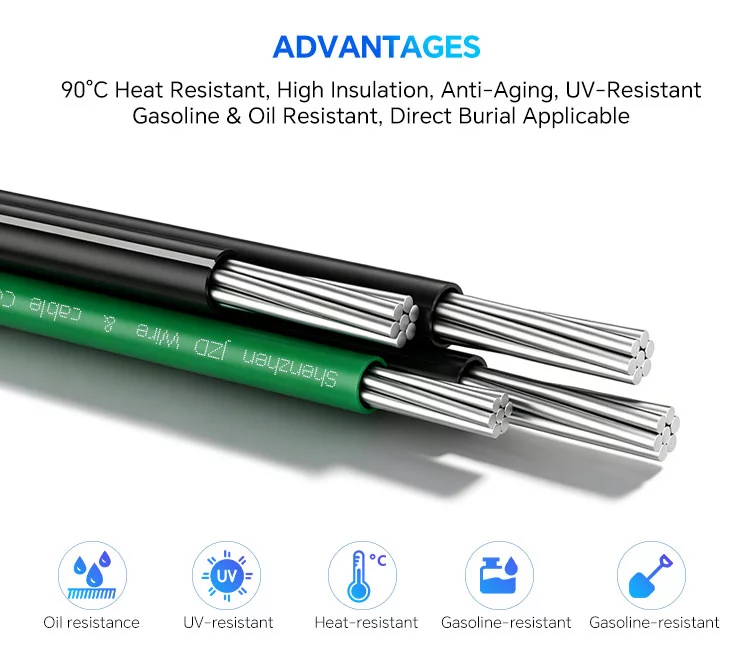
Mobile home parks require a reliable feeder system to distribute power from a central service point to individual home site pedestals. NEC Article 550 requires each mobile home lot feeder to have a minimum ampacity of 100A.
These feeder runs often involve long underground installations, making conductor sizing and voltage drop important considerations. Aluminum conductors are widely used because they offer a cost-effective and lightweight solution for large feeder applications when properly sized and installed according to NEC requirements.
Aluminum Alloy: AA-1350 vs. AA-8000 Series
NEC 310.14 requires aluminum conductors used in building wiring to be AA-8000 series alloy. This is not optional—conductors must be listed as AA-8000.
1. AA-1350 (Obsolete for Building Wire)
AA-1350 was the standard aluminum conductor alloy in the 1960s and 1970s. It was used in solid conductor branch circuits (#10, #12 AWG) on terminals designed for copper. The failure mechanism was thermal expansion mismatch:
- Aluminum expands more than copper under load
- Repeated thermal cycling causes terminals to loosen
- Loose connections create high resistance and overheating
- Copper-aluminum galvanic corrosion accelerated the process
AA-1350 is no longer permitted for building wire applications per NEC 310.14.
2. AA-8000 Series (Current Standard)
AA-8000 series alloys have different properties:
| Property | AA-1350 | AA-8000 Series |
| Thermal expansion coefficient | Higher | Lower (closer to copper) |
| Creep resistance | Poor | Superior |
| Tensile strength | Lower | Higher |
| Termination compatibility | Poor | Designed for UL-listed AL/CU terminals |
AA-8000 series conductors are not “better copper.” They are a different material engineered for the specific demands of building wire applications. When properly terminated, AA-8000 feeders have a field performance record comparable to copper.
Conductor Sizing: Ampacity and Temperature Rating
1. NEC Table 310.15(B)(16) – Three Temperature Columns
Table 310.15(B)(16) lists ampacities at 60°C, 75°C, and 90°C insulation temperature ratings. USE-2 cable is rated 90°C in wet and dry locations (see Section 7 for the “-2” designation). This means the conductor can run continuously at 90°C without damaging the insulation.
However, NEC 110.14(C) controls the actual ampacity used for sizing.
For circuits rated 100A or less, the ampacity is based on the 60°C column if the termination is not marked otherwise.
For circuits rated over 100A, the ampacity is based on the 75°C column. Most breaker lugs and equipment terminals are rated 75°C.
This is the most common sizing error in mobile home feeders. Using the 90°C column for sizing a circuit over 100A is incorrect.
2. Aluminum Ampacity at 75°C (for Circuits Over 100A)
Conductor sizes are based on the 75°C column in Table 310.15(B)(16):
| Conductor Size (AWG/kcmil) | 75°C Ampacity | 90°C Ampacity (for reference) |
| 2 AWG | 90A | 100A |
| 1 AWG | 100A | 115A |
| 1/0 AWG | 120A | 135A |
| 2/0 AWG | 135A | 150A |
| 3/0 AWG | 155A | 175A |
| 4/0 AWG | 180A | 205A |
| 250 kcmil | 205A | 230A |
Key implication: #2 AWG aluminum is not a 100A conductor—it is rated 90A at 75°C. A 100A feeder requires #1 AWG aluminum.
3. Continuous Loads and the 125% Rule
Continuous and non-continuous loads must be treated differently for sizing. NEC 210.19(A) requires branch circuit conductors supplying continuous loads to be sized at 125% of the continuous load current.
For mobile home feeders, if the lot load is continuous (3 hours or more), #1 AWG (100A ampacity) may be insufficient for an 80A continuous load (80A × 125% = 100A—exactly at rating, with no margin). Engineering practice recommends 2/0 AWG for continuous loads above 80A.
| Load Current | Load Type | Sizing Current | Minimum Aluminum Conductor (75°C) |
| 80A | Non-continuous | 80A | #1 AWG (100A) |
| 80A | Continuous | 100A | 2/0 AWG (135A) |
| 100A | Non-continuous | 100A | #1 AWG (100A) |
| 100A | Continuous | 125A | 2/0 AWG (135A) |
Engineering recommendation: Treating mobile home lot loads as continuous is the more conservative and prudent approach—2/0 AWG is recommended for 100A services when continuous loading is expected.
Feeder Configurations: Quadruplex Assembly
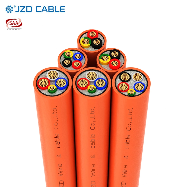
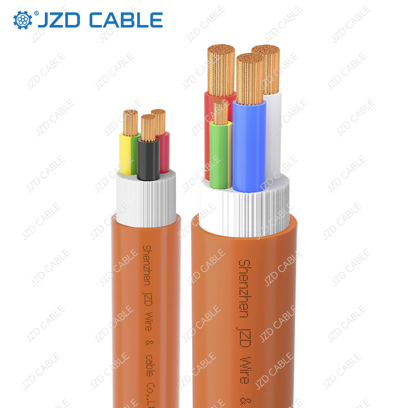
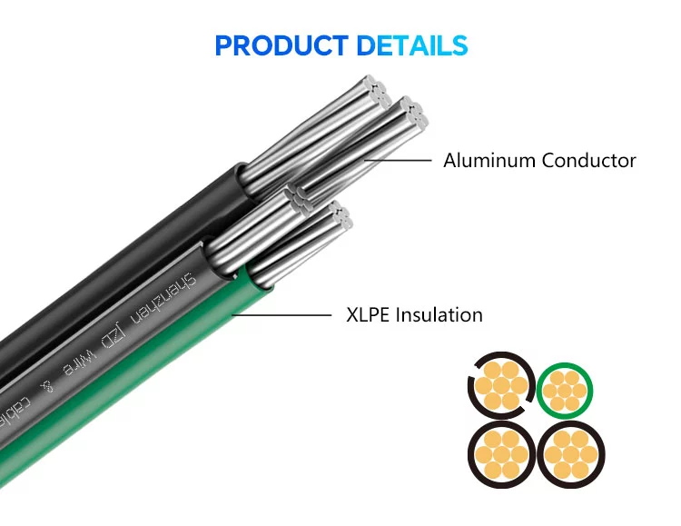
Mobile home feeder cable is typically supplied as a quadruplex assembly—four conductors cabled together:
- Two phase conductors (insulated, color-coded)
- One neutral conductor (insulated, color-coded)
- One equipment grounding conductor (insulated, green)
The neutral conductor may be downsized per NEC 220.61. For a single-phase, 3-wire feeder, the neutral carries only the unbalanced load. In a balanced system, the neutral current is zero. NEC allows the neutral to be smaller than the phase conductors, with minimum size based on:
- Largest unbalance load
- 70% demand factor for neutral sizing
The equipment grounding conductor is sized per NEC Table 250.122, based on the overcurrent device rating.
Common configurations:
| Assembly Code | Phase Conductor | Neutral | Ground | Application |
| 2-2-4-6 | #2 AWG | #4 AWG | #6 AWG | 100A feeder (phase conductors must be protected at 90A) |
| 1-1-2-4 | #1 AWG | #2 AWG | #4 AWG | 100A feeder (full 100A ampacity) |
| 2/0-2/0-1-4 | 2/0 AWG | #1 AWG | #4 AWG | 125A feeder |
| 4/0-4/0-2/0-4 | 4/0 AWG | 2/0 AWG | #4 AWG | 200A feeder |
Voltage Drop Calculation
Ampacity and voltage drop are independent sizing constraints. The conductor must satisfy both—the larger of the two governs the final selection.
NEC does not mandate voltage drop limits in the code text (except for fire pumps), but the informational note recommends 3% for feeders and 5% total for feeders plus branch circuits. Many local codes and contract specifications adopt these values as requirements.
1. DC Resistance Method for Single-Phase Feeder
For a single-phase, two-wire or three-wire feeder (load balanced between phases), the voltage drop formula is:
VD = (2 × L × R × I) / 1000
Where:
- VD = voltage drop (volts)
- L = one-way length (feet)
- R = conductor DC resistance at 75°C (ohms per 1000 ft, from NEC Chapter 9 Table 8)
- I = load current (amperes)
For aluminum conductors at 75°C, the resistance values (from NEC Chapter 9 Table 8) are:
| Conductor Size | DC Resistance at 75°C (Ω/1000 ft) |
| 1 AWG | 0.253 |
| 2/0 AWG | 0.159 |
| 3/0 AWG | 0.126 |
| 4/0 AWG | 0.1 |
| 250 kcmil | 0.084 |
2. Example Calculation: 100A Feeder, 200 ft, 240V
Condition: 100A continuous load, 200-foot one-way distance, 240V single-phase service. Target voltage drop ≤ 3%.
Trial conductor: #1 AWG aluminum
- Resistance = 0.253 Ω/1000 ft (from NEC Chapter 9 Table 8 at 75°C)
- VD = (2 × 200 × 0.253 × 100) / 1000 = 10.12V
- VD% = 10.12 / 240 = 4.2% → Exceeds 3% limit
Trial conductor: 2/0 AWG aluminum
- Resistance = 0.159 Ω/1000 ft
- VD = (2 × 200 × 0.159 × 100) / 1000 = 6.36V
- VD% = 6.36 / 240 = 2.65% → Compliant
Result: A 100A feeder at 200 ft requires 2/0 AWG to meet 3% voltage drop, not #1 AWG (which would be the ampacity-only selection).
3. General Rule of Thumb for Aluminum Feeders
For 240V single-phase feeders:
| Conductor | Maximum Length for 3% VD at 100A |
| 1 AWG | ~130 ft |
| 2/0 AWG | ~210 ft |
| 3/0 AWG | ~260 ft |
Conduit fill must be checked separately under NEC Chapter 9 when upsizing for voltage drop beyond ampacity requirements.
Aluminum Cable Installation: Critical Requirements
1. Termination Lugs
Terminals must be AL/CU dual-rated. This is standard on modern panels and meter pedestals. Look for “AL/CU” or “AL9CU” marked on the lug.
Do not terminate aluminum directly onto terminals not rated for aluminum. This is not a recommendation—NEC 110.14(A) requires terminals used for aluminum to be marked.
2. Anti-Oxidant Compound
NEC 110.14 does not explicitly require anti-oxidant compound. However, most breaker manufacturer installation instructions require it for aluminum terminations. Under NEC 110.14(D), manufacturer instructions are mandatory.
Compound should be applied to the conductor after cleaning and before insertion into the lug. Common products: Noalox (Ideal), Ox-Gard (Gardner Bender), Penetrox (Burndy).
3. Torque Specifications
NEC 110.14(D): Terminations must be tightened to the manufacturer’s specified torque value. This value is typically printed on the breaker label or in the installation manual.
Under-torquing causes high-resistance connections and heating. Over-torquing can strip threads or stress the lug body. Both are common failure modes.
4. Conductor Preparation
- Clean the conductor immediately before installation
- Use a wire brush or abrasive pad—do not use sandpaper (silicon carbide can embed in aluminum)
- Apply anti-oxidant immediately after cleaning
- Insert fully and torque to specification
USE-2 Cable: Specifications and Code Reference
USE-2 cable is listed under UL 854 and falls under NEC Article 338 (Service Entrance Cable, USE Type). It is manufactured with:
- Aluminum conductors (AA-8000 series, per NEC 310.14)—the AA-8000 series alloy discussed in Section 2.2 is the material used in this product
- XLPE insulation (cross-linked polyethylene)
- UV-resistant outer jacket for sunlight exposure
- 90°C temperature rating in both wet and dry locations (the “-2” designation is specific to USE/RHH/RHW: -2 indicates 90°C wet/dry; USE without -2 is only 75°C wet)
The cable is also listed as RHH/RHW-2, meaning it can be used in conduit installations as well as direct burial.
USE-2 is not a building wire for interior branch circuits under NEC 334 (NM cable) or 336 (TC cable). It is specifically for underground service and feeder applications, including mobile home park lots, where it terminates at the meter pedestal or panel.
1. Direct Burial Depth (NEC Table 300.5)
USE-2 cable is rated for direct earth burial without conduit. Minimum cover depths:
| Location | Minimum Depth | NEC Reference |
| One- and two-family dwelling driveways | 18 inches | Table 300.5, Column 4 |
| Areas not subject to vehicle traffic | 24 inches | Table 300.5, Column 3 |
| Under streets, parking lots | 24 inches | Table 300.5, Column 3 |
Note: Local amendments may require greater depths. Check with the authority having jurisdiction (AHJ).
2. Conductor Identification
Phase conductors on USE-2 cable are typically black and red, the neutral is white or gray with a stripe, and the ground is green. Color coding must comply with NEC 200.6 for neutral identification and 250.119 for equipment grounding conductor identification.
JZD’s USE-2 Aluminum Cable for Mobile Home Feeders
Based on the requirements outlined above—AA-8000 series aluminum alloy, 90°C wet/dry temperature rating, UL certification, and direct burial capability—USE-2 is the cable that checks every box. JZD Cable manufactures exactly that.
JZD Cable produces UL-certified USE-2 direct burial cable specifically designed for demanding outdoor and underground applications.
Product Specifications
| Feature | Specification |
| Certification | UL 854 |
| Voltage | 600V |
| Conductor | Aluminum (AA-8000 series) |
| Insulation | XLPE (cross-linked polyethylene) |
| Temperature rating | 90°C in wet and dry locations (the “-2” rating) |
| Direct burial | Yes, no conduit required |
| Sunlight resistance | UV-resistant |
| Triple-rated | RHH/RHW-2/USE-2 |
Key Benefits
- UL-listed and code-compliant: Meets UL 854, NEC Article 338, and NEC Article 310
- AA-8000 series aluminum: Meets NEC 310.14 requirements for modern aluminum alloy
- Direct burial rated: Eliminates the cost and labor of conduit installation
- Sunlight and weather resistant: UV-resistant jacket ensures long-term outdoor durability
- Durable XLPE insulation: Cross-linked polyethylene provides excellent moisture, chemical, and mechanical resistance
- 90°C wet rating: The “-2” rating means full 90°C performance in wet locations
With over 25 years of manufacturing experience and exports to over 100 countries, JZD Cable provides reliable, code-compliant aluminum feeder cable solutions for mobile home park projects worldwide.
Conclusion
Aluminum feeder cable has become the standard choice for mobile home park power distribution for four reasons:
- Cost: 50-70% less than copper for equivalent ampacity
- Weight: One-third the weight of copper, simplifying installation
- Modern alloy: AA-8000 series (required by NEC 310.14) eliminates the reliability issues of 1960s-era AA-1350 alloy
- Code compliance: Fully permitted by the NEC when properly sized and terminated
NEC Articles 310 and 550 provide the framework for sizing these feeders, with minimum 100A ratings, demand factor allowances, and clear conductor sizing guidelines. A critical takeaway: always use the 75°C column for sizing—most terminations are rated 75°C, and #2 AWG aluminum is only 90A at 75°C, not 100A.
Need aluminum USE-2 cable for your mobile home park project? Contact JZD for technical specifications, sizing assistance, and certified cable solutions.