


In industrial and commercial power distribution projects, the run from the main cable tray to the equipment often presents a choice: conduit, or a cable rated for exposed installation. The cost of conduit is not just the raceway itself. It includes elbows, fittings, pulling labor, and construction time. When the distance is short and the path is open, the material and labor for conduit often exceed the cost of the cable itself.
TC-ER cable allows exposed installation outside the tray without full conduit coverage. This article focuses only on TC-ER: what it is, why it can be installed exposed, where it is suitable, how to calculate ampacity, and what to verify during installation and selection.
What TC-ER Is
1. Definition
TC-ER falls under UL 1277 for tray cable. Standard TC cable must remain inside the tray; once it leaves the tray, conduit protection is required. TC-ER adds “ER” — Exposed Run — meaning it has passed additional mechanical tests and is qualified for exposed installation outside the tray.
2. Application Scope
The direct benefit is that short transitions from tray to equipment can eliminate conduit. But TC-ER is not a universal cable. Its application is concentrated in exposed wiring for industrial and commercial power distribution. It does not replace conduit in all scenarios.
Why It Can Be Installed Exposed
1. Mechanical Testing
The ER rating is not a product label. It is proof that the cable has passed two mechanical tests specified in UL 1277.
The crush test requires the cable to withstand 1,000 lbf applied by a flat steel plate onto the cable placed over a steel rod. The impact test requires the cable to withstand 260 ft-lbf of impact energy. The pass criteria are not that the jacket remains uncracked, but that under the specified crush and impact conditions, there is no contact between circuit conductors, or between circuit conductors and the grounding conductor.
In practical terms: a footstep, a dropped tool, or accidental equipment contact must not cause an internal short circuit. Standard TC cable has not passed these two tests because its design assumes continuous installation in a tray or conduit, with mechanical protection provided by the external structure.
2. Construction That Supports the Rating
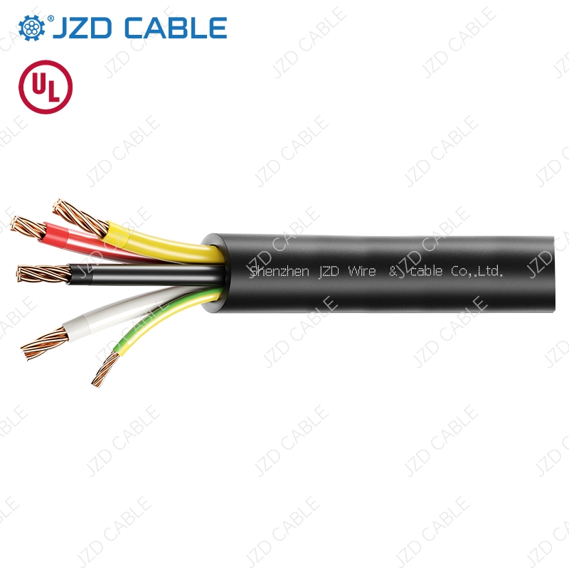
TC-ER construction supports this performance. The conductor is annealed copper per ASTM B3 or B8, with sizes from 14 AWG to 750 kcmil, available in single or multi-conductor configurations. Insulation is XHHW-2 cross-linked polyethylene, rated 90°C wet and 90°C dry. The cross-linked structure of XLPE does not rely on plasticizers, so insulation resistance remains more stable under long-term moisture exposure. The jacket is PVC, providing sunlight resistance, abrasion resistance, and impact protection. A grounding conductor is built into the cable assembly, as required by NEC for all TC-ER installations.
Construction and mechanical performance determine where TC-ER can be used. The next section covers its suitable applications.
Where It Is Suitable
1. Tray-to-Equipment Transitions
The typical application for TC-ER is the transition from tray to equipment. The cable leaves the tray and enters a motor, control panel, or distribution box without intermediate conduit. This is the core use case for TC-ER.
2. Industrial and Commercial Wiring
Exposed wiring along walls, ceilings, or structural frames in industrial plants also commonly uses TC-ER. In workshops with dispersed equipment and irregular paths, conduit is time-consuming and labor-intensive; direct installation with TC-ER is more flexible.
In commercial buildings, power connections for air handling units, pumps, and fans can reduce conduit usage when the equipment is close to the tray.
3. Outdoor Use
Outdoor use is also possible, provided the jacket carries a sunlight-resistant rating. Rooftop equipment feeders and outdoor panel entries can use TC-ER with a sunlight-resistant jacket.
4. VFD Circuits
For VFD circuits, standard TC-ER is a general-purpose tray cable. Whether it is suitable depends on the drive manufacturer’s requirements. Specific verification points are covered in the selection section below.
Once the application is determined, the next step is calculating conductor size, which means ampacity correction.
How to Calculate Ampacity
1. Starting from the 90°C Column
TC-ER insulation is rated 90°C, so ampacity can start from the 90°C column in NEC Table 310.16. But the final allowable ampacity requires three correction steps.
2. Termination Temperature Limitation
NEC 110.14(C) states that conductor ampacity cannot exceed the termination temperature rating. Most industrial circuit breakers have terminations rated 60°C or 75°C. If the cable is rated 90°C but connected to a 75°C termination, the ampacity must be based on the 75°C column.
3. Ambient Temperature Correction
Table 310.16 is based on 30°C ambient. In high-temperature workshops or rooftop exposed installations, ambient temperatures above 40°C are common. For 90°C insulation, the correction factor at 40°C ambient is approximately 0.91.
4. Bundled Conductor Derating
When more than three current-carrying conductors are inside the cable, derate per NEC Table 310.15(C)(1). When multiple cables are densely arranged in a tray, heat dissipation is worse, and bundled derating cannot be ignored.
5. Worked Example
For a 10 AWG copper TC-ER, the correction process is as follows:
| Step | Correction | Result |
| Start | 90°C column base value | 40A |
| Step 1 | 75°C termination limit | 35A |
| Step 2 | 40°C ambient ×0.91 | ~31.9A |
| Step 3 | 6 current-carrying conductors bundled ×0.80 | ~25.5A |
If the 90°C column value of 40A is used directly, the conductor may be undersized and operating temperature may exceed limits.
Once conductor size is determined, bending radius and support during installation directly affect cable life.

Installation Notes
1. Bending Radius
The minimum bending radius for multi-conductor TC-ER is typically 12 times the outer diameter. This value is much larger than for single-conductor building wire because the cabling structure, fillers, and jacket of a multi-conductor cable are more prone to core displacement, jacket wrinkling, and insulation damage under excessive bending.
2. Support Requirements
A dedicated support is required at the tray exit. The cable must not be allowed to sag on its own to form a bend. The bending radius at turns is calculated based on cable outer diameter, not on the overall diameter of the cable bundle or the tray width. When cables are bundled, each cable must independently maintain its minimum bending radius. The bending space of a single cable should not be compressed just because the bundle looks neat.
Based on the technical considerations above, the following checklist can be used for selection and verification.
What to Verify During Selection
1. Core Checklist
When specifying TC-ER, confirm the following:
- UL 1277 listing covering crush and impact test requirements
- UL 44 test report for XHHW-2 insulation, confirming 90°C wet / 90°C dry rating
- Voltage rating matched to the system (600V or 1000V)
- Sunlight-resistant jacket rating for outdoor use
- Built-in equipment grounding conductor
- Direct burial marking if required by the project
- Batch consistency in jacket thickness, conductor stranding, and marking
2. VFD Circuit Considerations
For VFD circuits, also confirm whether the cable includes symmetrical grounding conductors and shielding. Standard TC-ER is a general-purpose tray cable without these features. Some TC-ER products are also qualified for VFD applications. Selection should confirm shield coverage and symmetrical grounding conductor configuration against the drive manufacturer’s requirements.
3. 2026 NEC Revision to 336.10(7)
The 2026 NEC revision to 336.10(7) added “raceways” and “enclosures” to the list of locations where unsupported transitions are permitted, bringing the code closer to common installation practice. This revision recognizes the frequent configuration where TC-ER exits a tray, enters a short conduit or terminal box, and continues to the equipment, while maintaining the 6-foot limit and the requirement for mechanical support at the transition point. If the project involves such transitions, this can be used to confirm compliance boundaries.
Conclusion
The value of TC-ER is that it allows exposed installation outside the tray, reducing conduit usage. Its ER rating is verified through crush and impact tests, and the XHHW-2/PVC construction provides stable insulation performance in wet and high-temperature environments. During selection, ampacity should be corrected step by step starting from termination temperature limits, the need for shielded TC-ER should be confirmed based on the application, and bending radius should be determined at 12 times the outer diameter. These considerations together determine whether TC-ER can meet compliance, ampacity, and long-term reliability requirements in a project.
For UL 1277 listed TC-ER cable specifications or certification documents, please contact us.