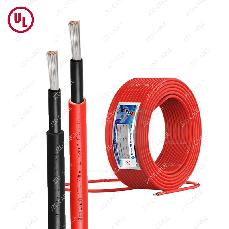



According to IEC 60245-4, H07RN-F rubber flexible cables are designed for applications requiring flexibility, mechanical durability, and reliable performance under demanding conditions. In telecom tower applications, cables must withstand UV exposure, moisture, vibration, and temperature variations to maintain long-term power reliability.
Once a tower cable fails, the cost of remediation far exceeds the cable’s price. And these failures often go unnoticed until they happen—by then, the price has already been paid.
To understand why H07RN‑F is the right choice for tower applications, we first need to examine the specific stresses tower cables endure.
Four Key Stresses on Tower Cables
1. Continuous Tensile Creep from Vertical Runs
Towers typically range from 30 to over 100 meters in height. Power cables run vertically from the base to the top, supporting their own weight over the entire run. Under this sustained tensile load, conventional cable conductors and sheaths gradually creep—conductors stretch and thin, insulation compresses, and sheaths deform permanently. Over time, conductor resistance increases, voltage drop exceeds equipment tolerance, and RRUs eventually drop out due to undervoltage.
In one documented case, an RRU measured only 46.5‑47.5V at the equipment end (nominal 48V system). The investigation found that the power feeder was 250 meters long with sheath damage. The only fix was to reroute and shorten the feeder. Per 5G base station power supply standards, the total voltage drop on a 48V DC system must remain ≤3.2V—cable resistance degradation directly determines whether the system can meet this requirement.
2. Wind‑Induced Vibration and Fretting Wear
Towers oscillate continuously under wind loading, with both low-amplitude sway and high-frequency micro-vibrations. At 100 meters, the top of a tower can sway several meters in strong winds. Cables attached to the tower vibrate with it, and at fixing points (cable ties, clamps), constant fretting occurs. Over time, this seemingly minor repeated abrasion wears through the sheath, eventually exposing the insulation.
The situation is compounded in the 5G era, where each RRU requires its own power cable and fiber. Cable counts on towers have surged. Multiple cables routed in parallel within confined spaces rub against each other and against the structure, accelerating sheath wear.
3. Extreme Temperature Differentials and UV Exposure
Vertical temperature gradients on towers are significant. On a sunny summer day, tower steel surfaces at the top can exceed 70°C, while the equipment shelter at the base may sit at 25°C. In winter, the top may face -40°C, while the base benefits from equipment heat. Different sections of the same cable experience extreme temperature differences simultaneously, and the resulting thermal expansion and contraction create cumulative mechanical stress.
At the same time, tower cables are exposed to direct sunlight year‑round. Standard PVC‑insulated cables degrade under prolonged UV exposure, becoming brittle and cracking. One operator reported sheath cracking on tower cables after only 3 years in service—the root cause was identified as “cable shielding and sheath not using UV-resistant materials.”
4. RRU Power Supply Characteristics: Low Voltage, High Current, Long Distance
Unlike most industrial equipment, RRUs typically operate on ‑48V DC. For the same power, the current is far higher than on a 220V AC system. Example: a three‑sector site with each RRU drawing about 800 W, total power around 2.4 kW—at ‑48 V, current reaches 50 A. Long feeder distances mean substantial voltage drop challenges.
Cable conductor resistance directly determines whether the RRU receives adequate voltage. Increased resistance from cable aging, plus contact resistance from oxidized terminations, can push the voltage at the RRU outside its acceptable operating window. H07RN‑F’s Class 5 stranded conductors use high‑purity annealed copper, with DC resistance strictly compliant with IEC 60228. At a given cross‑section, resistance values are stable and predictable. This is the foundation for accurate voltage drop calculations and reliable equipment‑end power delivery.
How H07RN‑F Addresses These Stresses
| Tower Stress | Typical PVC Cable Outcome | H07RN‑F Response |
| Vertical tensile creep | Conductor stretches, resistance increases, voltage drop exceeds limits | EPR insulation + neoprene sheath resist creep; Class 5 stranded conductor distributes stress |
| Wind‑induced fretting | PVC sheath poor abrasion resistance; wears through in 3‑5 years | Neoprene sheath high abrasion resistance + fatigue resistance |
| High temperature at top (70°C+) | PVC softens and deforms; insulation performance degrades | EPR/neoprene stable up to 90°C |
| Low temperature at top (‑40°C) | PVC becomes brittle, cracks on bending | Stable down to -40°C in fixed installation |
| UV exposure (year‑round direct sun) | PVC degrades; sheath cracks | Neoprene is UV‑resistant; no degradation |
| Service life on tower | Signs of aging in 3‑5 years | 10+ years stable operation |
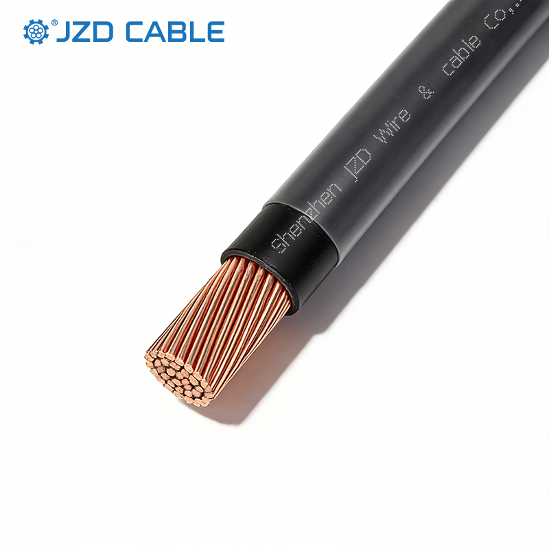
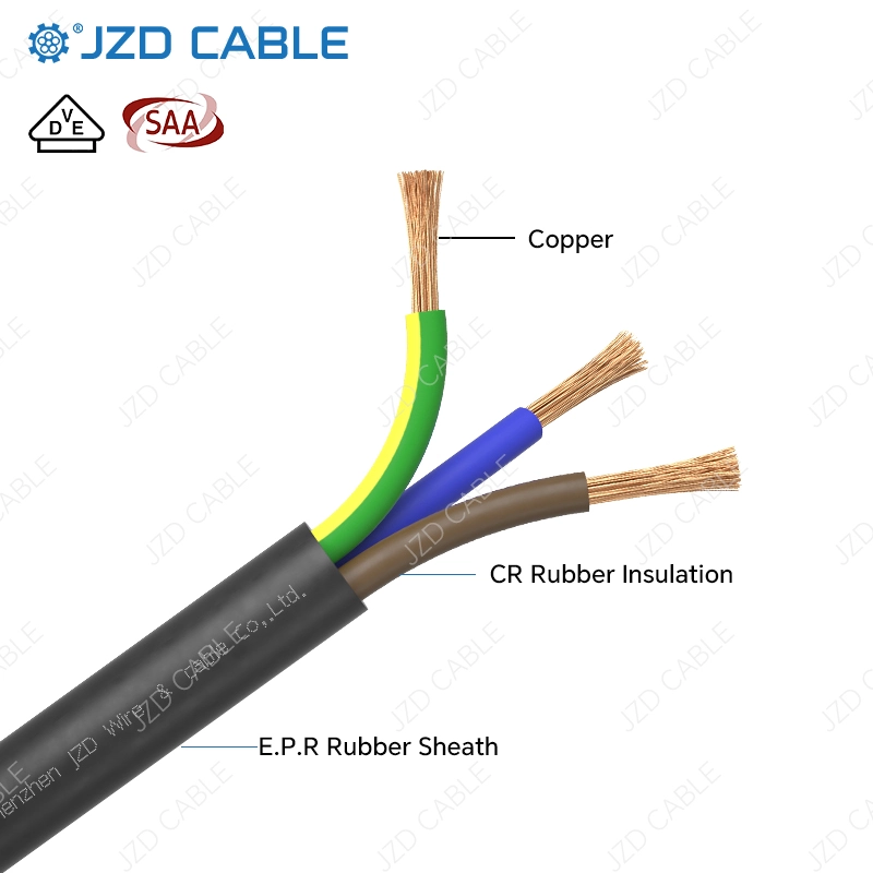
The “RN” in H07RN‑F tells the story: “R” stands for EPR (ethylene‑propylene rubber) insulation, and “N” stands for neoprene (chloroprene rubber) sheath. EPR delivers excellent electrical properties and thermal stability, with continuous operating temperature up to 90°C. The neoprene sheath handles UV, ozone, oil, and mechanical wear. The Class 5 stranded conductor, made of multiple fine copper strands, distributes tensile stress more effectively in vertical runs—even when tower vibration causes displacement, stress concentrations do not develop in the conductor.
Tower Cabling Best Practices: From Base to Top
With the right cable, installation quality is equally critical to reliability. The following outlines key considerations for tower cabling using H07RN‑F.
1. Base Section—Equipment Shelter to Tower Footing
Cables exit the shelter and enter vertical trays or ladder racks at the tower base. A drip loop (U‑bend or water drip) should be installed at the shelter exit to prevent water from following the cable into the shelter. At the tower footing, cables should be routed in protective conduits or trays to prevent foot traffic damage and rodent chewing.
2. Vertical Section—Tower Climb
This is the most critical segment. Cables run vertically and must support their own weight while resisting wind‑induced vibration.
- Fixing spacing: recommend 1.5‑2 meters between fixing points to distribute tensile load evenly.
- Fixings: use wide‑face nylon ties or purpose‑built cable clamps—narrow ties can embed in the sheath over time. Allow slight axial slip within the clamps (to let self‑weight stress release naturally) while maintaining radial retention.
- Bends: at tower cross‑braces or diagonal members, maintain bend radius of no less than 6× cable OD for dynamic conditions, with an additional fixing point on each side of the bend.
- Abrasion protection: where cables contact tower steel, add rubber sleeves or PVC protection to prevent sheath wear from long‑term vibration.
3. Top Section—Antenna Platform to RRU
Cables transition from vertical runs to equipment platforms and connect to RRUs.
- Leave sufficient service loop (typically 0.5‑1 meter) at the RRU end to allow for re‑termination during future maintenance.
- At cable entry to junction boxes or equipment interfaces, install strain relief clamps to prevent cable weight from pulling on terminations.
- Seal junction boxes or waterproof connectors thoroughly after termination.
4. Voltage Drop Calculations Are a Non‑Negotiable Sizing Criterion
Per 5G base station power supply standards, total voltage drop on a 48V DC system should remain ≤ 3.2V. Cable cross‑section selection must satisfy current‑carrying capacity, voltage drop, and mechanical strength simultaneously. Precise calculations must be performed for each site based on actual tower height, equipment power consumption, and feeder length. The mindset of “close enough” during sizing is often the root cause of undervoltage site outages later on.
Why Tower Cable Replacement Costs Far Exceed the Cable Price
Buyers often focus on unit prices, overlooking the fact that cable material cost is a small fraction of total cost of ownership (TCO) on a tower.
Take a typical tower power cable replacement scenario:
| Cost Component | Relative Weight |
| Cable material | Minor |
| At‑height labor (specialized crew) | Significant |
| Access equipment (boom truck / crane) | Significant |
| Service interruption losses (SLA penalties + customer impact) | Potentially dominant |
The material cost of the cable itself is negligible compared to the logistics, specialized labor, and potential service disruption penalties involved in a tower replacement. A cable that fails prematurely can cost an operator tens of thousands in site visits and lost revenue.
In contrast, a properly specified H07RN‑F, correctly installed, can run for 10+ years on a tower. The incremental cost of selecting a robust rubber cable at the outset is marginal compared to the costs of a single unplanned replacement. The economics are clear: quality pays for itself many times over.
It is precisely these field lessons and cost realities that have shaped the typical application profile of H07RN‑F in tower power distribution.
Typical H07RN‑F Applications in Telecom Towers
- Power feed from tower base to equipment shelter. From the utility connection point to the shelter, the cable’s weather resistance ensures long‑term outdoor performance.
- Vertical tower runs to RRUs. This is the most demanding application—cables must handle self‑weight, wind‑induced vibration, and extreme temperatures.
- Short‑run connections between top‑of‑tower equipment. Flexibility is required for routing in confined spaces on the antenna platform.
Selection Reference: Key Parameters and Certifications
H07RN‑F from JZD is VDE, HAR, and CB certified. Key parameters for tower applications:
- Conductor: Class 5 extra‑fine stranded annealed copper—excellent flexibility and bending fatigue resistance
- Insulation: EPR (ethylene‑propylene rubber)—continuous operating temperature 90°C
- Sheath: Heavy‑duty black neoprene (CR)—UV, ozone, oil, and abrasion resistant
- Operating temperature: ‑40°C to +90°C (fixed installation)
- Flame retardancy: IEC 60332‑1‑2, CPR Eca rated
- Environmental: RoHS compliant, lead‑free
JZD exports to over 100 countries and regions, including North America, Europe, Australia, and Southeast Asia, and can supply UL, SAA, and TUV certified products upon request.
Related Reading: One CB Certificate for H07RN-F – Global Access
Conclusion
Telecom towers are the physical backbone of communications networks, and power cables are the vessels that keep them running. On the vertical path from base to top, cables face UV, temperature extremes, vibration, tensile stress, and the passage of time.
H07RN‑F rubber cable—with EPR insulation, neoprene sheath, Class 5 stranded conductor, and wide temperature range—addresses each of these challenges. It is not the cheapest option, but it is the reliable choice that makes “10‑year maintenance‑free tower cable” achievable.
Contact JZD for technical support and certified H07RN‑F cable solutions for your tower projects.